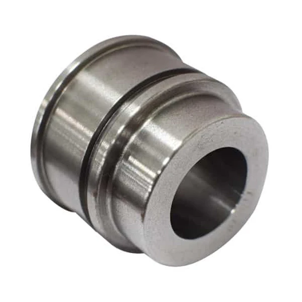
When a hydraulic cylinder leaks, heavy production lines grind to a halt—triggering severe, compounding hourly financial losses. Repeatedly replacing blown seals is just a band-aid; when a cylinder keeps failing, the fix belongs in the machine shop, not the toolbox. Permanent prevention requires addressing the true root causes: machining tolerances and material specifications.
Catastrophic failures like seal extrusion, rod side loading, and barrel ballooning are entirely preventable. By specifying precise H7/f7 machining fits, maintaining a strict piston rod surface finish between Ra 0.1 and 0.2 μm, and upgrading to high-yield E355 cold-drawn seamless tubing, you can eliminate structural expansion under extreme pressure spikes through our premium hydraulic cylinder components
This ultimate guide bypasses the surface symptoms to analyze the exact mechanical root causes of cylinder failure, giving you the precision engineering solutions needed to protect your heavy machinery investments.
Table of Contents
Introduction: The Economics and Logic of Failure Analysis
The Real Cost of Downtime
Heavy machinery procurement teams often fall into a dangerous trap by focusing entirely on the invoice cost of a replacement cylinder. When a critical line down occurs in a steel mill or a mining site, a standard $500 component stops being a minor line item. It becomes the exact point of failure that grinds millions of dollars of capital infrastructure to a complete halt.
If a primary hydraulic excavator cracks a cylinder gland in the field, the resulting operational paralysis triggers compounding losses reaching upwards of $2,000 per hour. Relying on cheap, unhardened steel components to save on initial procurement budgets is a direct math error that forces your operation to absorb massive, unpredictable downtime expenses.
Symptom vs. Root Cause
Most trading companies will sell you a standard seal kit and tell you the problem is fixed. This basic advice treats a major mechanical failure like a superficial cut, applying a temporary band-aid to a systemic structural defect. A blown polyurethane seal lip or a deeply scored wear band is never the true origin of a hydraulic failure; it is merely the final visible symptom of an unresolved underlying issue.
If your supplier machined the cylinder gland on a manual 6140 lathe with excessive spindle runout, the resulting concentricity deviation will force the piston rod to deflect under every heavy stroke. Swapping the ruined polymer for a new seal without addressing this dimensional error condemns the entire asset to a repetitive cycle of catastrophic blowout within weeks of redeployment.
Fluid Contamination, Oil Quality & Aeration Issues
Abrasive Particulate Contamination
Environmental dust, airborne silica, and internal systemic wear debris constantly infiltrate the active hydraulic oil loop during heavy field operations. When these hard contaminant particles match the precise dynamic clearance gaps between sliding elements, massive component degradation begins immediately. These operational clearance zones between the reciprocating piston rod and the internal gland bore typically measure between 1 and 10 microns. Trapped within this microscopic boundary, the rigid silica fragments act exactly like micro-cutting tools that continuously plow the finished metal surfaces during every extension and retraction stroke.
This destructive cutting action inflicts deep linear micro-scratching across the piston rod, effectively turning a bright mirror chrome finish into a frosted, hazy surface. As the scarred rod cyclically retracts back into the cylinder assembly, these sharp metallic ridges and trapped particles rapidly shred the delicate sealing lips of your high-pressure polymers.
Preventing this structural destruction requires maintaining a high standard of hydraulic fluid cleanliness across your entire operational circuit. Procurement teams must implement and enforce strict oil target specifications matching or exceeding the ISO 4406 standard of 16/14/11.
Installing high-efficiency, multi-stage filtration networks—such as dedicated off-line kidney loops within the reservoir circuit—keeps micron-sized particulate matter isolated. Furthermore, maintenance managers must mandate the absolute pre-filtering of all new fluid added to the reservoir because standard barrel oil arriving from a refinery is never clean.
Moisture & Chemical Fluid Degradation
Water ingress past degraded wiper seals or heavy condensation inside the fluid reservoir triggers severe chemical oil breakdown over high-cycle operating periods. This water contamination accelerates thermal oxidation, a destructive process that rapidly elevates the Total Acid Number (TAN) of the hydraulic fluid. High TAN values trigger catastrophic hydrogen embrittlement within the steel crystal structure and chemically destroy crucial elastomeric polymer bonds inside the primary seals.
The visible symptoms of this chemical attack include deep internal pitting along the steel cylinder barrel bore, accompanied by widespread corrosion on all unplated internal components. Over time, the primary sealing elements completely lose their material integrity, becoming gummy, soft, and spongy under pressure.
To prevent chemical fluid failure, you must install active desiccant breathers on reservoirs to capture atmospheric moisture before air enters the tank. Operations should also establish a regular scheduled oil analysis program to track water content in parts-per-million (ppm) and monitor shifting TAN values before the fluid turns corrosive.
Cavitation & Micro-Dieseling (The Hidden Thermal Killer)
When restricted return lines choke oil flow or pumps pull in external air through degraded suction seals, low-pressure vapor bubbles form within the fluid stream. As these unstable vapor pockets move rapidly from low-pressure suction areas into high-pressure working zones, they collapse instantly under the load. This sudden adiabatic compression causes localized bubble temperatures to skyrocket up to 1,000°C, triggering an immediate micro-combustion of the surrounding fluid molecules known as the micro-dieseling effect.
This hidden thermal process leaves distinct, carbonized black burn marks and scorched spots across the polyurethane seal lips, stripping the polymer of its elasticity. The violent micro-implosions also erode the surrounding metal, creating honeycomb-like micro-pitting across the internal faces of the piston, gland, and valve ports.
You can eliminate this thermal destruction by enforcing thorough air bleeding protocols during initial machine commissioning. Our production crew machines dedicated air-bleed valves at the highest physical elevation points of the cylinder body to vent trapped air pocket volumes. Finally, maintenance teams must check suction line seal integrity regularly to eliminate air ingestion pathways before micro-combustion occurs.
Seal Failure, Wear, and Degradation
Mechanical Extrusion and “Nibbling”
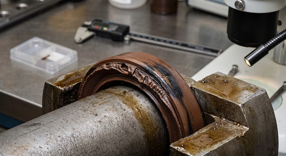
High system pressures and sudden, unbuffered hydraulic spikes easily destroy soft elastomeric sealing components. When internal fluid forces exceed the structural limits of your polymer, the system forces the flexible material directly into the tight clearance gap behind the seal assembly. Engineers call this critical hazardous zone the maximum allowable extrusion gap, or E-gap, located between the heavy piston gland and the internal barrel wall.
Under this persistent shearing, the seal heel quickly ends up ragged, frayed, or chewed to pieces. Every extension stroke shaves off microscopic fragments of the polymer matrix until the raw sealing edge fails completely.
Stopping this breakdown before it starts comes down to one thing: holding flawless machining tolerances from day one. My husband personally configures our 6150 CNC lathes to hold rigid H7/f7 or H8/f7 engineering fits, reducing the physical E-gap to a microscopic boundary.
For high-pressure heavy machinery setups operating above 25 MPa, you must also insert hard thermoplastic anti-extrusion back-up rings made of premium POM, Nylon, or PEEK directly behind the primary polymer to block material migration.
Thermal Degradation (“Heat Cooking”)
Continuous high-cycle operations at temperatures above the thermal boundary of your polymer accelerate internal structural aging. Extreme localized heat also builds up rapidly due to high-frequency friction along the fast-moving reciprocating shaft. This extreme thermal overload speeds up polymer cross-linking, stripping the base material of its essential elasticity.
Out in the field, this cooking process leaves the soft seals hard, brittle, and severely cracked across their structural profiles. The ruined component suffers a permanent compression set, flattening the original seal geometry until it can no longer exert positive radial force against the running surface.
To end this thermal degradation, procurement managers must optimize cooling circuits to keep target fluid temperatures below 65°C. For severe, high-heat industrial deployments, you should upgrade standard polyurethane compounds to chemically inert, high-temperature alternatives like Viton/FKM or specialized low-compression nitrile formulations.
Installation Damage (Cuts & Tears)
A massive percentage of immediate, high-pressure fluid leaks on freshly rebuilt cylinders comes down to careless installation damage during workshop assembly. This premature failure happens when maintenance technicians force delicate, dry seal lips over sharp machined shoulders, un-deburred fluid ports, or exposed casing screw threads.
These sharp steel edges act like razor blades, slicing small nicks or deep cuts into the critical sealing edge. Even a tiny 0.5 mm surface scratch across the polymer lip destroys its sealing integrity, creating an immediate fluid bypass pathway as soon as the cylinder experiences its first operational load.
Preventing assembly damage requires implementing precise engineering geometries before any component leaves our factory floor. Our production crew machines exact 15 to 20-degree assembly chamfers on all entry points and meticulously radiuses all internal cross-drilled fluid ports.
Finally, your maintenance shop must enforce the absolute use of specialized assembly tools, plastic installation sleeves, and polished metal bullet tools over exposed rod threads to shield the polymer during insert procedures.
Rod Misalignment, Side Loading, and Rod Selection
Structural Side Loading & Deflection
Mechanical travel paths often deviate from the true load trajectory during heavy field movements. This shifting alignment transfers severe lateral forces directly into the piston rod, effectively bending internal components out of their concentric centerlines. When an operating machine forces an unbalanced weight distribution onto the expanding shaft, the structural deflection concentrates extreme pressure onto one side of the internal assembly.
Under this uneven pressure, localized one-sided wear patterns quickly destroy bronze guide bushings while tearing glass-filled nylon piston wear bands apart. As the misaligned shaft strokes repeatedly, deep linear gouges cut directly into the internal barrel wall to cause sudden mechanical binding during field operations.
Trading companies sell standard cylinders with rigid fixed pins. A rigid mount cannot handle real-world structural shifting. Permanent prevention requires using the correct rods paired with appropriate mounting hardware.
Engineering teams must transition to robust spherical rod-end bearings and heavy-duty clevis mounts to eliminate structural twisting. These spherical joints allow autonomous self-alignment during multi-axis movements, ensuring the rod travels cleanly along its intended centerline. Additionally, installation teams should verify alignment with industrial laser tracking tools during final assembly to guarantee structural accuracy under load.
Rod Bending & Buckling
Catastrophic rod bending occurs under intensive compressive forces when the applied load exceeds the Euler buckling limit during the extension stroke. This destruction happens instantly when operators overload heavy machinery, or when poor cylinder design features an improper stroke-to-diameter ratio.
Excessive axial compression causes permanent plastic deformation, forcing the bent piston rod to jam violently against the internal gland. This structural failure seizes the piston tightly within the honed tube and ruins the entire assembly.
In my 15 years of running this factory, I have seen buyers fail when they choose standard, untreated 45# carbon steel. They select cheap raw steel for long strokes without any induction hardening to save on initial budgets. Stopping this buckling requires upgrading the core material and adding internal mechanical support.
DREJEX builds heavy-duty rods from 42CrMo4 steel and high-tensile AISI 4140 steel. Our workshop heat-treats, quenches, and tempers the metal for superior yield strength. Long-stroke designs exceeding 1,500 mm also require internal steel stop tubes to distribute lateral load forces across a broader surface area.
Surface Optimization
Choosing the proper rod finish requires a precise engineering balance between friction reduction and positive fluid retention. When the metal surface is ground too smooth below Ra 0.05 μm roughness, the steel cannot retain the essential lubricating oil film required to coat the dynamic sealing zone. This completely dry interface triggers intense seal stiction, causing the cylinder to jerk violently during low-speed movements in an operational defect called slip-stick chatter.
Conversely, running a rough finish acts exactly like coarse sandpaper that rapidly shreds the polymer sealing lip during high-frequency cycles. This continuous abrasive tearing creates immediate fluid pathways, forcing high-pressure hydraulic oil to weep past the external gland wiper.
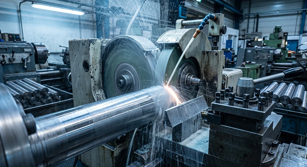
Suppliers often leave rods with a unidirectional polish from manual lathes. At DREJEX, our co-founder and chief technical master precision-calibrated our centerless grinding setup to eliminate this micro-geometry flaw entirely. Every piston rod undergoes multi-stage centerless grinding and cross-hatch polishing to maintain a strict surface finish between Ra 0.1 and 0.2 μm. This specific micro-geometry holds just enough fluid molecules to lubricate the dynamic polymer interface perfectly without allowing external leaks.
System Overpressure, Pressure Spikes, and Tube Quality
Hydraulic Shock & Structural Overload
Sudden load shifts unleash violent kinetic shockwaves across the hydraulic loop. These spikes happen when the moving piston slams into its limit under load. The trapped oil creates an instant pressure surge above the system rating. This massive energy transfer easily tears through the tensile strength of steel.
Under these explosive shocks, hairline fatigue cracks rapidly grow across the weld toes. The extreme internal pressure shears the matching casing threads off the gland.
Fix this destruction by checking manufacturer ratings during machine setup. Operators must never push systems beyond the stamped nominal working pressure.
We eliminate this issue by machining adjustable hydraulic cushioning inside the end-caps. These internal channels restrict oil flow to slow the piston before impact. Adding high-performance accumulators to the circuit safely absorbs the remaining fluid surge.
Barrel “Ballooning” (Tube Expansion)
Severe internal pressure spikes destroy low-grade steel barrels by stretching walls permanently. The intensive fluid forces push the metal past its material yield point. This action causes a permanent radial expansion called barrel ballooning. The damage concentrates in the middle area of the stroke.
The piston seals lose tight contact with the expanded internal wall. High-pressure oil blows straight past this swollen mid-stroke zone. Your machine loses lifting capacity, but the cylinder holds pressure at both ends.
Preventing permanent metal deformation comes down to selecting high-quality cylinder tubes for high pressure. We calculate required wall thickness with Lamé thick-walled formulas. We always apply a strict safety factor of three or higher.
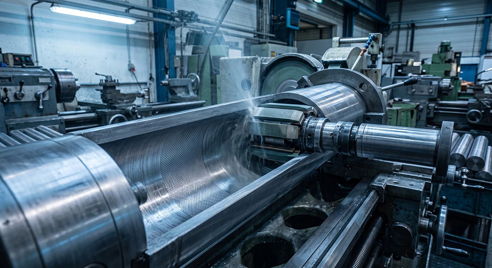
DREJEX rejects cheap welded rolled tubes from low-end trading suppliers. We buy raw cold-drawn seamless tubing like ST52.3 steel from prime mills. We also run premium DOM E355 steel for heavy operational loads. Our heavy-duty machines hone these bores to a strict Ra 0.4 μm finish. This careful processing keeps the internal barrel round under extreme surges.
Corrosion, Environmental Damage, and Site Conditions
Chrome Delamination & Electrochemical Pitting
Outdoor machinery constantly faces harsh weather conditions on heavy industrial sites. Corrosive media like marine salt spray easily penetrates standard hard chrome plating. When airborne acids seep through the natural micro-cracks, electrochemical reactions attack the base steel. The galvanic reaction breaks the atomic bond, forcing the hard plating layer to flake off.
Widespread rusted pits appear across the bare metal rod, creating rough abrasive surfaces. These jagged metallic ridges immediately shred new gland seals during every single retraction stroke.
Prevent electrochemical pitting by knowing your operating environment before ordering your cylinder components. DREJEX builds heavy-duty rods featuring induction-hardened base surfaces with 50 to 55 HRC hardness. The induction case depth measures 1 to 2 mm to resist flying stone impacts. For extreme deployments, we apply double chrome plating or advanced laser cladding coatings.
Physical Impact & Mechanical Flying Debris
When flying rocks strike the extended rod, the blunt force creates deep surface gouges. These heavy impacts leave raised metal burrs and sharp dents across the polished steel.
The jagged metal burrs physically obstruct smooth travel while passing through the gland assembly. These sharp steel edges slice directly through the polymer seals to cause immediate external leaks.
DREJEX blocks physical debris using custom-engineered mechanical deflector shields and heavy steel shroud guards. For flexible protection, we install heavy-duty rubber bellows boots over the extending rod assembly. These durable covers completely isolate the polished metal surface from airborne contaminants and mechanical impacts.
Design, Specification, and Maintenance Management

Fatigue Fracture & Stress Concentration
High-cycle machinery movements create continuous cyclic stress along the piston rod. Sharp internal corners concentrate heavy structural stress at the main thread shoulder step. Under high cyclic loads, micro-cracks form instantly along these un-deburred geometric shoulders. Tiny cracks grow steadily through the steel profile until the rod breaks completely.
Many buyers fail when choosing components with sharp internal corner designs. Trading companies skip crucial radius machining steps to cut workshop cycle times. At DREJEX, we avoid this structural failure by implementing precise engineering design rules. We machine a smooth 2.0 mm stress-relief radius on every thread shoulder step. Our 6150 CNC lathes cut smooth radiuses to distribute heavy loads evenly.
Thread Stripping & Piston Connection Preload
Heavy hydraulic pressure pushes against the piston, forcing the main thread connection to stretch. Loose assembly tolerances allow tiny microscopic movements inside the internal piston thread joint. Over time, these small shifts strip the raw steel threads completely under load. The piston detaches inside the honed barrel, smashing through the front gland.
Stopping thread stripping requires managing the precise assembly torque during the connection stage. Our workshop utilizes heavy-duty hydraulic torque wrenches to lock the piston thread tight. We apply specific torque limits based on the thread diameter size.
We also select the correct industrial liquid anaerobic threadlocker for each cylinder type. Standard machinery requires a high-strength permanent red compound on the main piston threads. Maintenance teams need localized heat above 250°C to disassemble this joint later. Medium-strength blue lock fluid seals smaller internal set screws to prevent vibration loosening.
System Oil Flushing & Maintenance Protocols
Residual machining chips and welding slag remain inside new hydraulic lines after assembly. Starting the main system pump pushes these loose contaminants straight into the cylinder valves. The trapped abrasive grit destroys fresh polymer seals within hours of machine activation.
Eradicating premature seal failure depends entirely on proper hydraulic system maintenance before operations begin. Maintenance crews must execute a dedicated high-velocity oil flushing circuit bypass for 48 hours. High-velocity fluid circulation washes away internal welding slag before you connect the lines.
The MRO Precision Quality Inspection Matrix
Before final deployment, you must verify all critical assembly checkpoints.Our workshop enforces this precision parameters checklist to permanently eliminate premature field leaks.
| Parameter Checklist | Target Specification / Tolerance Metric | Prevention Purpose |
| Rod Straightness (Runout) | Maximum runout must measure ≤0.1 mm per 1000mm length. | Eliminates localized side loading and prevents internal guide binding. |
| Bore Roundness (Ovality) | Bore dimensions must fall within H7 or H8 tolerance limits. | Prevents high-pressure internal fluid blow-by across swollen zones. |
| Rod Surface Finish | Maintain rod finish between Ra 0.1 and 0.2 μm with cross-hatch lines. | Ensures optimal oil film retention while preserving seal lifespan. |
| Bore Surface Finish | Target a honed cross-hatch pattern of Ra 0.4 μm. | Retains dynamic boundary lubrication for wear bands to avoid galling. |
| Quality Control Testing | Run low-pressure bypass and high-pressure static hold tests. | Guarantees absolute zero-leak internal and external sealing integrity. |
Hardcore Heavy Machinery Hydraulic FAQs
Q1: Why do brand-new seals fail immediately after an MRO cylinder rebuild?
More often than not, the culprit is incorrect surface roughness or unaddressed barrel ballooning. Standard manual lathes leave a unidirectional polish on the metal. The smooth surface cannot retain the essential lubricating oil film. Dry operation creates intense seal stiction and shreds the polymer lip. Always verify the rod finish stays between Ra 0.1 and 0.2 μm.
Q2: When should procurement managers specify 42CrMo4 steel over standard 45# carbon steel?
Long-stroke applications exceeding 1500 mm require high-tensile 42CrMo4 or AISI 4140 steel. Standard 45# steel fails under heavy axial loads during extension strokes. The upgraded alloy provides superior yield strength against permanent plastic deformation. Upgrading the core steel prevents catastrophic bending failures on industrial sites.
Q3: How does the maximum allowable extrusion gap affect high-pressure cylinder lifespan?
High system pressures force flexible seal polymers into the clearance gap. Operating above 25 MPa shaves off micro-pieces of the soft material. We configure our 6150 CNC lathes to maintain rigid H7/f7 engineering fits. Strict tolerance control reduces the dynamic E-gap to a minimum.
Q4: Why is micro-dieseling called the hidden thermal killer of hydraulic cylinders?
Restricted suction lines choke oil flow and form low-pressure vapor bubbles. These vapor pockets move quickly into high-pressure zones to collapse under load. Sudden adiabatic compression drives localized bubble temperatures to 1000°C. The intense thermal surge leaves carbonized black burn marks across polyurethane lips.
Q5: What is the fastest way to eliminate structural side loading in field operations?
Transition from rigid fixed mounts to robust spherical rod-end bearings immediately. Spherical joints allow autonomous self-alignment during complex multi-axis movements. The piston rod travels cleanly along its intended centerline under heavy loads. Verify final installation tracking with industrial laser tools to prevent twisting.
Direct Factory Technical Assessment
Send your technical drawings directly to our workshop for an exact factory assessment. We review your specified tolerances and material grades within 24 hours. Get direct source pricing from DREJEX without any trading middlemen.