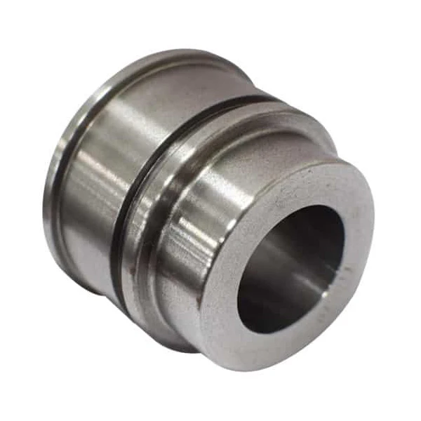
Using free online calculators often leads to expensive mistakes. You input your bore size and pressure. The tool predicts 10 tons of force. However, the physical cylinder stalls under an 8-ton load. This failure happens because formulas ignore factory reality. A simple equation cannot measure friction on rough metal. It ignores bad machining tolerances. We must calculate your force using real-world factory standards.
Table of Contents
Before You Use a Hydraulic Cylinder Force Calculator: The Factory Truth
A 4-inch bore at 3000 PSI should yield 37,699 pounds of force. This is the theoretical limit. In reality, you will never see this full output. A cheap lathe leaves the barrel finish at Ra 0.8. We require Ra 0.4. This surface roughness creates heavy seal friction. Friction eats 10% of your power before the rod even moves.
Calculation errors usually stem from ignored tolerance gaps. If a machinist misses the H7 tolerance mark, the fit is loose. Hydraulic fluid bypasses the piston seal under high pressure. This internal leakage makes the cylinder feel weak. A perfect hydraulic cylinder force calculator cannot fix a leaking barrel.
Verify the machining equipment before you trust the math. DREJEX’s technical co-founder brings 15 years of precision machining experience. We use heavy 6140 and 6150 lathes to hit exact specs. Precise metal cutting ensures your real-world force matches your calculation. Poor machining turns a simple formula into a costly failure.
How Do You Measure a Hydraulic Cylinder? (Dimensions First)
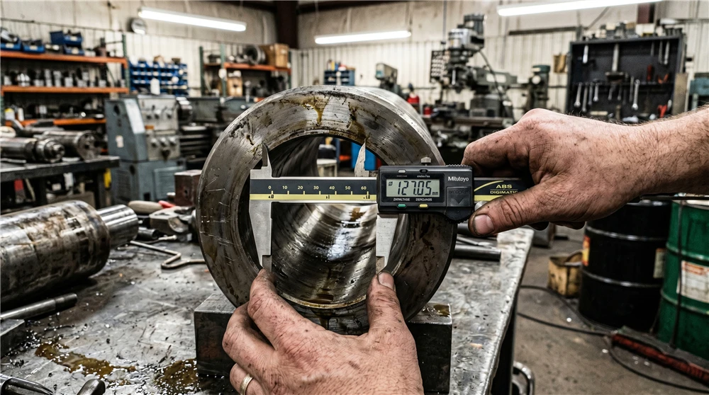
Wrong measurements lead to failed calculations. Measuring the outer shell of the barrel instead of the inner bore diameter (ID) is a common mistake. This ID is the key variable for the diameter formula for cylinder area. Using the outer diameter (OD) makes your force calculation too high. Your machine will stall under a heavy load.
How to Measure a Hydraulic Cylinder Correctly
Use calibrated digital calipers to find the exact inner width of the barrel. At DREJEX, we check these dimensions on our 6140 lathes during production. We do not just measure once. We check for circularity at multiple points along the bore. If the tube is not perfectly round, the seals will leak within weeks. Precision measurement prevents internal pressure loss.
Identifying Stroke Length and Cylinder Height
The formula for the height of a cylinder is often misunderstood in hydraulics. In this industry, height refers to the stroke length. You do not need a complex formula to find this. Instead, you simply measure the distance the rod travels. Measure from the fully retracted position to the fully extended position. During long strokes, thin tubes can bulge or bend. We use 45# steel for our barrels to prevent this deformation.
Small errors in hydraulic cylinder measurements cause big problems. A 2mm mistake can change your force output by 15%. Verify your technical specifications with a factory expert before you buy. Our engineers use the correct equation for diameter of a cylinder to guarantee your machine’s power.
The Core Force Area Equation: Area of a Piston
Hydraulic force is the direct product of pressure and the area of a piston. Selecting the correct force area equation is the first step in determining cylinder performance. However, the calculated output only translates to actual power when the piston meets high precision standards. A piston with poor tolerances causes pressure drops that no formula can predict. To prevent this, DREJEX machines every area piston on 6150 lathes, ensuring the surface is perfectly flat and the geometry is exact.
The Piston Area Formula Explained
The piston area formula calculates the specific surface where pressurized oil applies its load. The calculation uses the inner bore diameter (D) or the radius (r) as the primary input:
Alternatively, using the diameter
Variable Definitions:
• D: Inner Bore Diameter (ID)
• r: Radius of the Bore
Mixing metric and imperial units is a fast way to fail. You must use a single unit system for every measurement. Even a minor unit error results in a weak hydraulic force that fails to meet your machine’s requirements in the field.
Why Precision Fit Matters for Force
For the calculations to hold true, the piston must maintain a perfect seal against the barrel. DREJEX holds H7 tolerances for all internal components to prevent “oil bypass”—the primary cause of force loss. If the gap between the piston and the barrel wall is too large, the seal will deform under heavy loads. Our CNC-machined pistons ensure that the piston force calculation performed during the design phase matches the actual force delivered in the field. Without this precision fit, your result remains a theoretical maximum rather than a guaranteed output.
How to Calculate Force of Hydraulic Cylinder (Push vs. Pull)
Hydraulic force output is never symmetrical. A cylinder is inherently stronger during extension (push) than during retraction (pull). This variance is caused by the physical volume the piston rod occupies inside the barrel. Failing to calculate the “effective area” for both directions is a leading cause of system failure in the field.
Calculating Extension Force (The Push)
During the extension stroke, high-pressure oil fills the entire base of the cylinder, acting upon the full area of a piston. This creates the maximum tonnage the unit can deliver. For instance, a design requiring a 20-ton lift depends entirely on this total bore surface area. However, high force creates high stress; this is why using 45# quenched and tempered steel for piston rods is critical. This material grade ensures the rod does not buckle or deform when the cylinder is pushing at its peak rated capacity.
Calculating Retraction Force (The Pull)
During retraction, the oil acts upon the “rod side” of the piston. Because the rod is attached here, the available surface area—known as the Annular Area—is significantly reduced. To find the actual pull force of a hydraulic cylinder, the cross-sectional area of the rod must be subtracted from the total piston area.
The Pull Force Formula:
Because this effective area is smaller, the hydraulic pull force will always be lower than the push force at identical pressures. If you ignore the rod’s diameter during the design phase, the cylinder will likely stall or move erratically when attempting to retract under a load. Balancing the rod-to-bore ratio is the final technical step to achieving reliable, two-way performance.
Hydraulic Cylinder Pressure vs. Force: The PSI Factor
Hydraulic cylinder force is the direct output of system pressure acting upon the piston’s surface area. While increasing the PSI (pounds per square inch) or Bar raises the tonnage, pressure must remain within the cylinder’s structural limits. Exceeding these rated thresholds risks catastrophic failure, including seal blowout, barrel deformation, and dangerous high-pressure fluid leaks.
Calculating Theoretical vs. Actual Force
The following equation determines the total load capacity based on hydraulic input and cylinder dimensions:
Technical Variables:
• Force: The total mechanical load delivered (typically in lbs or Newtons).
• Pressure: The system’s relief valve setting (PSI or Bar).
• Area: The effective surface (Bore or Annular) defined by the cylinder’s geometry.
The Engineering Risks of Hydraulic Intensity
Using excessive system pressure to compensate for an undersized cylinder bore is a high-risk design shortcut. Operating at the edge of a cylinder’s pressure rating accelerates seal wear and increases “blow-by”—where pressurized oil bypasses the piston, causing the load to drift or drop.
Furthermore, internal friction within the barrel consumes 5% to 10% of the theoretical force. Minimizing this resistance requires high-tensile carbon steel (AISI 1045) and a precision-honed internal surface. Without these specifications, the energy intended for movement is converted into heat. Excessive heat degrades hydraulic oil and hardens seals, leading to premature system failure. For long-term reliability, the industry standard is to utilize a larger bore at a lower operating pressure rather than stressing components to their limits.
Hydraulic Pressure to Tonnage Calculator: Converting PSI to Lifting Force
Online tools calculate pressure in pounds. Shop floors operate entirely in tons. This unit difference creates dangerous confusion. A standard pressure to tonnage calculator hides the true physical load. One recent client trusted a free web tool. Their undersized cylinder cracked a heavy machine base. Our factory turned a massive 45# steel replacement to restore their production.
The conversion requires a simple hydraulic press formula. Multiply the system PSI by the piston area. This calculation yields the total force in pounds. Divide this exact number by 2,000. The final result is the US standard tonnage. This specific math calculates lifting force accurately. A 40,000-pound load perfectly matches a 20-ton cylinder.
A reliable design requires a 20% safety margin. Metal bends quickly under extreme shock loads. Surviving these heavy loads demands a rigid 6150 lathe. Turning the 45# steel rod here prevents future bending. The cylinder barrel also needs a strict H7 tolerance. Loose machining blows the polyurethane seal under peak pressure. A theoretical 20-ton rating always fails without an Ra 0.4 surface finish.
How to Calculate the Weight and Capacity of a Cylinder
Calculating exact cylinder weight stops unexpected international freight bills. This final shipping cost depends entirely on total metal volume. Multiplying this volume by carbon steel density yields the massive mass of a 45# steel rod. Hollowing out this heavy rod reduces freight but destroys structural strength. Maintaining solid material prevents physical bending under extreme shock loads. Thick barrel walls also add necessary weight to stop explosive high-pressure failures. Paying high freight costs simply guarantees this physical field safety.
A hydraulic cylinder never pulls fluid from an empty void. It relies entirely on the oil reservoir of a connected power unit. The cylinder’s internal bore and stroke dictate this total fluid demand. A gallon calculator cylinder tool reveals the exact volume required for full extension. Calculating capacity of a cylinder matches this fluid demand to the pump perfectly. A mismatched small reservoir empties completely before the stroke finishes. The starving gear pump then sucks in empty air. These resulting air bubbles destroy expensive pumps instantly.
During production, machining depth directly alters this internal fluid capacity. Cutting a cylinder bore too wide creates hidden extra space. This unplanned extra volume demands more oil than the reservoir holds. A rigid 6140 lathe prevents this dangerous over-cutting during manufacturing. Holding the steel barrel to a strict H7 inner tolerance eliminates dimensional variations. This precise tolerance keeps the internal oil requirement perfectly stable. Stable oil demand prevents sudden system pressure drops in the field.
Pneumatic Air Cylinder Force Calculation vs. Hydraulic Force
When calculating force, online tools use identical math for air and oil. This shared equation mistakenly treats both fluids as solid materials. In reality, pressurized air acts like a soft mechanical sponge. Striking this trapped gas causes immediate physical compression. Such sudden volume loss instantly kills the lifting power. Without steady force, the entire machine stalls completely.
Unlike spongy gas, hydraulic oil completely resists volume compression. Trapped inside a cylinder, the fluid becomes extremely rigid. Violent mechanical shocks transfer directly through this liquid. Thin pneumatic aluminum tubes easily snap under these massive impacts. To survive such force, heavy industrial designs demand thick 45# steel. The table below exposes these critical hardware differences.
The Physical Reality: Air vs. Hydraulic Cylinders
| Technical Factor | Pneumatic (Air) Cylinder | Hydraulic (Oil) Cylinder | The Factory Consequence |
| Fluid State | Compressible (Acts like a spring) | Rigid (Acts like solid steel) | Air loses lifting force instantly. Oil transfers full mechanical shock. |
| System Pressure | 100 – 150 PSI | 3,000 – 5,000 PSI | Hydraulic systems easily blow out pneumatic seals. |
| Barrel Material | Thin aluminum extrusion | Thick 45# carbon steel | Aluminum tubes burst explosively under hydraulic pressure. |
| Inner Tolerance | Loose standard dimensions | Strict H7 tolerance | Loose machining causes immediate high-pressure oil bypass. |
| Surface Finish | Standard rough cut | Ra 0.4 mirror finish | Rough metal shreds polyurethane hydraulic seals quickly. |
| Machine Required | Light automated cutter | Heavy 6150 rigid lathe | Light machines cannot cut 45# steel accurately. |
Real World Physics: When Online Calculators Destroy Cylinders
Case 1: The Shock Load Barrel Bulge
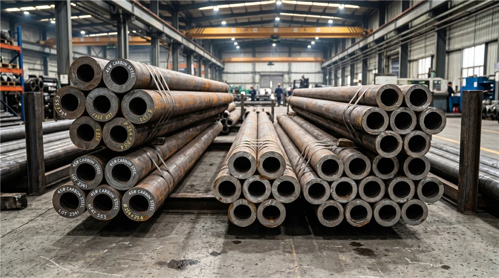
Hitting a mechanical hard stop multiplies the resting machine weight instantly. This sudden kinetic energy creates massive uncalculated force spikes. Without thick walls, extreme pressure stretches the cylinder barrel outward. Permanently deforming the internal bore ruins the perfect circular geometry. Inside this distorted tube, the metal edge shreds soft polyurethane seals. To survive such violent impacts, heavy 45# carbon steel is mandatory. A rigid 6140 lathe cuts this dense material safely.
Case 2: The Microscopic Seal Shredder
Cheap cylinder tubes often hide deep internal cutting grooves. Under high magnification, rough metal acts exactly like sandpaper. Scraping against these sharp microscopic peaks destroys soft polyurethane seals. Once those rubber barriers fail, high-pressure oil escapes the piston. Internal fluid bypass drops the mechanical lifting force immediately. To restore full lifting power, the barrel requires an Ra 0.4 finish. Here, heavy honing machines create the necessary mirror surface.
Case 3: The Fatal Tolerance Wobble
Pushing a massive physical load requires perfectly straight rod travel. Inside a loose barrel, the piston tilts slightly under extreme pressure. This uneven geometry creates dangerous lateral side forces. Forced off-center, the hard steel rod begins to wobble violently. Eventually, such lateral movement snaps the main metal shaft entirely. To prevent fatal rod fractures, manufacturers demand strict H7 tolerances. Rigid centerless grinding guarantees this perfectly straight outer diameter.
Conclusion: Turning Calculated Force Into Reliable Components
Tonnage formulas provide only a basic theoretical baseline number. In the field, violent mechanical shocks multiply this base force. Surviving such massive pressure spikes requires thick 45# carbon steel. To cut this hard metal, our factory utilizes heavy 6150 lathes. These rigid machines guarantee strict H7 internal component tolerances perfectly. Precise machining protects your custom pistons from catastrophic fluid leaks. Send your final hydraulic requirements directly to DREJEX. We manufacture reliable heavy-duty components for extreme industrial applications.
FAQS
1. Why do piston rod threads often snap under high pressure?
Extreme hydraulic force concentrates entirely on the small threaded connection point. Loose machining tolerances allow the piston to wobble during heavy movements. This slight lateral shifting creates massive fatigue stress on the metal threads. Eventually, uncalculated vibration violently shears the steel bolt head off. Preventing this fatal snap requires precise H7 thread fitment.
2. Does high operating speed require more calculated tonnage?
Moving heavy loads rapidly requires accelerating massive resting weights quickly. Fast acceleration demands significantly more kinetic energy than slow movements. Under high velocities, internal fluid friction also increases total pressure resistance. To overcome these combined forces, add a 20% safety margin. This extra power handles the aggressive momentum during rapid cycles.
3. Can quickly closing a valve damage my internal components?
Suddenly stopping fast-moving oil creates massive internal pressure waves instantly. This violent fluid hammer effect multiplies the normal operating load. Absorbing such extreme kinetic shocks severely stresses internal seals and joints. Without proper relief valves, this spike rips through standard rubber barriers. Heavy-duty DREJEX parts withstand these sudden hydraulic impacts safely.
4. How does the mounting style affect theoretical load limits?
Theoretical tonnage assumes a perfectly supported short metal rod. Using long stroke lengths introduces dangerous bending risks under load. Pivot mounts allow the cylinder body to swing freely during operation. This moving geometry easily pushes the extended shaft off center. To prevent fatal buckling, calculate column strength alongside basic pressure.
5. How do you verify the actual force before shipping?
CCalculated numbers never guarantee real-world physical performance on the shop floor. To prove exact tonnage, our factory utilizes heavy hydraulic test benches. Pressurizing the assembled components simulates extreme industrial field conditions perfectly. Holding maximum load for several minutes exposes any hidden internal leaks. Only fully verified rigid parts leave DREJEX.