Choosing wrong cylinder designs causes high-pressure fluid leaks and costly machine downtime. This complete guide breaks down every core factory component to help you select perfectly.
The main parts of a hydraulic cylinder include the cylinder barrel, piston, piston rod, cylinder head, and base. These components of a hydraulic cylinder work together to change fluid pressure into linear force. Seals and high-pressure ports also play key roles. They prevent oil leaks and manage fluid entry during heavy machine work.
Below is the technical breakdown of each critical component from a manufacturing perspective.

Table of Contents
Cylinder Barrel
The cylinder barrel is the main body of the hydraulic cylinder. It acts as a heavy-duty pressure vessel. This part holds the internal pressure during operation.
Factories make this component from high-pressure cold-drawn steel tubes. Common international materials include AISI 1020 steel and E355 steel. DIN 2391 St52.3 is also a good choice for heavy loads. The inner surface requires a very smooth surface. Skiving & Roller Burnishing (SRB) processes finish the inner bore. This reduces friction and extends seal life.
Heavy boring machines cut the inner bore. The internal diameter must meet exact standard dimensions. It usually targets an H8 or H9 tolerance level.
The surface roughness must reach Ra 0.2 to Ra 0.4 microns. Rough bores cause fast oil leaks. The seals will wear out quickly too. Therefore, the barrel is key among custom hydraulic cylinder components. It must withstand high fluid pressure without expanding.
Piston
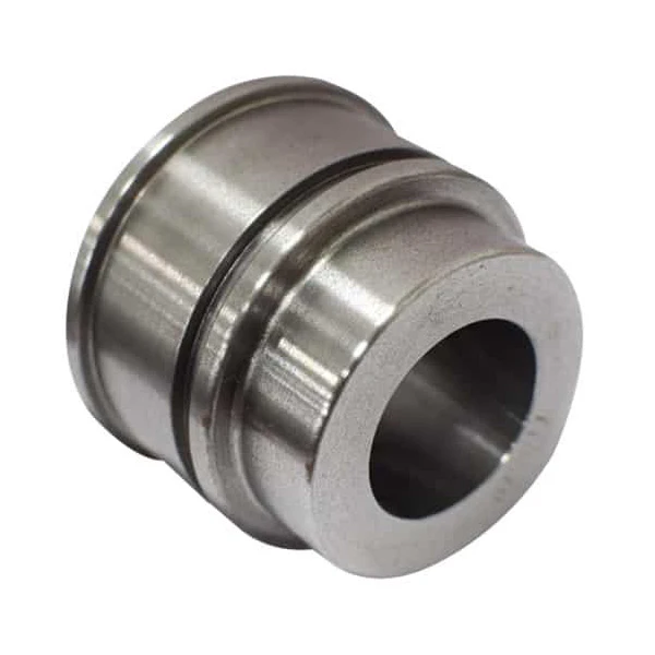
The hydraulic cylinder piston divides the internal barrel bore into two separate pressure chambers. Fluid pressure pushes against this component. This action creates linear movement. The piston transfers fluid energy directly to the rod.
Pistons are manufactured from ductile iron or carbon steel. Common international grades include EN-GJS-500-7 ductile iron or ASTM A536. AISI 1045 carbon steel is also standard. Heavy-duty CNC turning centers machine these raw metals.
The outer diameter needs a precise f7 or g6 tolerance fit. This precise shaft tolerance ensures a correct clearance fit inside the barrel bore. Incorrect cutting speeds cause bad surface finishes. Poor finishes quickly scratch the internal cylinder wall. The sealing grooves also require perfect concentricity alignment. Misalignment leads to uneven seal wear and sudden pressure loss.
Piston Rod
The piston rod is another critical hydraulic cylinder part. It connects the internal piston to the external machine load. This part transmits the linear force from the barrel bore. It must withstand extreme tensile and compressive stress during hard work.
Most trading companies will tell you standard chrome plating is enough. Here is the truth. A high-quality piston rod requires high-strength steel bars. Production uses AISI 1045 steel or 40Cr steel. This 40Cr steel is equivalent to AISI 5140 or EN 41Cr4. Induction hardening creates a tough case depth on the metal. The hardened layer must reach HRC 50 to HRC 55. This hard layer protects the metal from deep bending cracks.
Precision centerless grinding machines finish the outer diameter. Strict machine calibration ensures perfect roundness. The rod surface must achieve an f7 or g7 shaft tolerance. Electroplating adds a hard chrome layer to the surface. The chrome layer thickness must reach 20 to 30 microns. The micro-hardness of this chrome layer must exceed 850 HV. Scratches on this rod will quickly destroy the hydraulic seals. This grinding process also creates our precision transmission shafts.
Cylinder Head
The cylinder head is a vital hydraulic cylinder part. It covers the front part of the barrel bore. This component encloses the high-pressure fluid chamber. It must withstand massive shock loads during heavy operation.
High-strength materials are standard for this part. Common choices include AISI 1045 steel or EN-GJS-500-7 ductile iron. Heavy-duty CNC turning centers machine the mounting threads. Flange bolt holes also require precise spacing.
Poor thread precision causes thread stripping under heavy shock loads. Loose threads quickly unseat the static O-ring seal. This failure leads to a sudden fluid blowout. Therefore, face runout must stay under 0.03 millimeters. This accuracy ensures a solid mechanical lock with the barrel.
Gland
The cylinder gland positions the rod seals and internal wear rings. This component is installed within or bolted to the cylinder head. It guides the moving piston rod through the front assembly.
Piston rod glands are manufactured from EN-GJS-500-7 ductile iron or ASTM A536. Heavy-duty CNC turning centers machine the internal seal grooves. The internal guide bore requires an H7 or H8 tolerance fit.
Concentricity deviation causes rod deflection under high-pressure loads. This deflection quickly crushes the internal wear rings. The U-cup rod seal then tears from uneven friction. Fluid leaks out across the scored rod surface. Therefore, internal bore concentricity must stay under 0.02 millimeters.
Cylinder Base (Cap)
The cylinder base seals the rear end of the barrel bore. This component is also called a cylinder cap. It bears the full hydraulic force during high-pressure extension. Therefore, the base requires heavy material strength.
Production uses forged AISI 1045 steel for this hydraulic cylinder part. Cheap cast steel often contains internal porosity or blowholes. These hidden defects cause micro-cracks under deep pressure shocks.
Two main installation designs exist for these cylinder components. The cap is either welded directly or fixed with threads. Welded caps require deep welding penetration. Poor penetration causes sudden base separation during pressure spikes. Ultrasonic testing checks the weld joints before final assembly. This quality check guarantees zero structural failure at 30 MPa pressure.
Hydraulic Ports
Hydraulic ports are the gateways for high-pressure fluid. These ports are fluid entry points for components of a hydraulic cylinder. Standard port designs include SAE threads, NPT threads, and Metric threads.
Precision CNC vertical machining centers cut these mounting threads. Thread perpendicularity must remain within 0.02 millimeters. Trading companies often overlook internal thread burrs on this hydraulic cylinder part.
Worn tapping tools create sharp metal burrs inside the port. High-pressure fluid washes these loose burrs into the oil system. These metal particles quickly scratch the internal hydraulic seals. Blocked valve spools cause total system failure. Therefore, thread accuracy requires strict quality testing. Hardened thread plug gauges check every port after machining. Go and No-Go gauges verify the exact thread dimensions. This inspection ensures leak-free joints under 35 MPa pressure.
Seals and Seal Rings
Hydraulic seals prevent fluid leaks inside the system. These seals are critical components of a hydraulic cylinder. Standard seal types include U-cups, Glyd rings, and Step seals. Heavy-duty applications require premium polyurethane (PU) or fluororubber (FKM) materials. Low-tier suppliers often supply recycled rubber seals. These low-grade seals harden quickly at 120°C. They fail under high system pressure.
Proper seal function requires precise groove dimensions. CNC turning centers machine these seal grooves within the mating components. Groove surface roughness must reach Ra 0.8 microns. Rough groove walls scratch the soft seal edges. This damage causes severe internal pressure loss.
The wiper seal sits at the very front position. It scrapes dirt and dust off the moving rod. Foreign particles must not enter the cylinder bore. Clean oil protects all internal cylinder components. Premium seal kits maintain perfect zero-leakage performance under 40 MPa pressure.
Summary and Procurement Recommendations
Never purchase hydraulic components without exact technical prints. Low-grade parts fail instantly under heavy high-pressure loads. Sourcing directly from our Wenzhou facility removes middleman markups. Dimension errors do not occur with calibrated lathe equipment. Send your PDF drawings directly for an accurate factory evaluation. After final print confirmation, heavy production begins immediately.
5 Hardcore FAQs from Hydraulic Buyers
Q1: Why does a hydraulic cylinder rod scratch even with an 850 HV hard chrome plating?
Loose metal burrs inside hydraulic ports scratch the rod surface. Contaminated hydraulic oil also destroys the chrome layer during operation. Weak induction hardening causes deep base metal deformation. This core collapse cracks the outer chrome layer quickly.
Q2: What is the structural difference between a welded and a tie-rod hydraulic cylinder part?
Welded cylinders feature a barrel welded directly to the base. This compact design handles 35 MPa pressure in tight industrial spaces. Tie-rod cylinders use long external bolts for structural assembly. These units occupy more space but allow easier maintenance work.
Q3: How do you choose between AISI 1045 and AISI 4140 for a heavy-duty piston rod?
AISI 1045 carbon steel suits standard linear load applications perfectly. For severe mining impact, alloy steel is necessary. AISI 4140 contains chromium and molybdenum for superior tensile strength. This chemical composition prevents sudden rod breakage under extreme shock loads.
Q4: Why do hydraulic cylinder seals fail after only 3 months of high-pressure work?
Rough groove walls scratch the soft seal lips during continuous cycling. Concentricity deviation also creates severe uneven friction. High friction generates extreme local thermal stress over 120°C. This excessive heat destroys polyurethane seal kits rapidly.
Q5: Can a factory without ISO certification guarantee f7 and H8 tolerances for cylinder components?
Yes. Paper certificates do not machine raw steel bars. Heavy-duty machine rigidity determines the final dimensional precision. Strict micrometer calibration ensures an f7 or H8 tolerance fit. Correct centerless grinding setups achieve perfect roundness without commercial certificates.