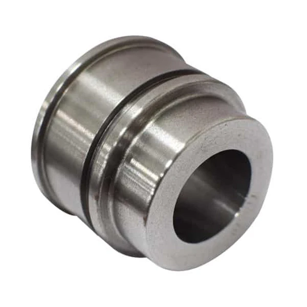
Heavy equipment mechanics face a massive challenge with stuck cylinder heads. They put a long pipe over a spanner wrench. This bad move destroys the gland pin holes immediately. It warps the steel cylinder barrel tube. Raw torque cannot break a galled thread joint. You must know machining tolerances for safe hydraulic cylinder head removal.
Table of Contents
Failure Modes & Diagnostic Framework
The Mechanics of a Seized Gland
A stubborn hydraulic cylinder head freezes inside the barrel tube. High working pressure creates immense stress between the head end and rod end. This constant hydraulic force deforms the micro-tolerances of the metal threads. Technicians measure this specific thread distortion on workshop lathes. Factory measurements prove micro-deformation causes the initial seize.
Chemical galling occurs under heavy operation. A machine operates above 3000 PSI. Grade 65-45-12 ductile iron gland threads rub against the 45# steel barrel threads. Micro-movement destroys the smooth surface finish. Without proper nickel-based anti-seize, the different metal molecules weld together.
Mechanical thread deformation also locks the cylinder parts. Excessive torque during past repairs stretches the thread pitch. This stretching destroys the original H7 tolerance fit between the gland and barrel.
Rust scaling builds up inside open work environments. Moisture enters the unsealed cylinder thread gap. The iron oxide expands. This expansion creates a high-friction mechanical wedge.
Factory anaerobic threadlockers require targeted heat to break. The cured glue will shear your pin wrench. The head looks removable but stays totally locked. You must learn how to remove stubborn hydraulic cylinder head parts with thermal tools.
Industrial Troubleshooting Table: 22 Workshop Failure Modes
Identification & Anatomy: Gland Mechanical Structures
Primary Retention Designs
| No. | Observed Symptom | Root Mechanical Cause | Factory Technical Fix |
| 1 | Gland rotates 10° then locks up. | Thread galling occurs on carbon steel tracks. | Chase threads on a 6150 lathe. Inspect barrel ID. |
| 2 | Gland pin holes tear under high torque. | Spanner pin slips out of the original 8mm holes. | Index 180 degrees. Machine new 12mm heavy-duty drive holes. |
| 3 | Barrel tube expands under torch heat. | Localized gas heating exceeds 300°C. | Use induction heating. Keep temperature at 250°C. |
| 4 | Retaining wire ring stays stuck in slot. | Debris blocks the internal groove clearance. | Press the gland 3mm deeper into the bore. |
| 5 | Gland backs out at an uneven angle. | Side load bends the internal thread pitch. | Mount on a lathe. Turn off the damaged gland. |
| 6 | Hydraulic oil leaks from the gland face. | High heat destroys the polyurethane rod seal. | Install a new seal. Verify Ra 0.4 finish. |
| 7 | Spanner wrench slips out of drive slot. | Repeated impact rounds off the sharp edges. | Recut driving slots to 90° with a mill. |
| 8 | Head moves but the rod remains jammed. | Internal piston assembly expands inside the tube. | Drain fluid. Apply low air pressure to rod. |
| 9 | Thread sealant turns into white powder. | Overheating destroys the metallurgical bond. | Measure barrel hardness. Scrap if steel is soft. |
| 10 | Gland face cracks under high torque load. | Cast iron material suffers from fatigue. | Machine a replacement gland from 45# steel. |
| 11 | Oil boils at the head port during removal. | Trapped pressure remains behind the gland. | Open the bleed port. Release fluid pressure safely. |
| 12 | Retaining ring snaps inside the barrel bore. | Heavy rust scale wedges the metal ring tight. | Inject penetrating oil. Apply light air hammer vibration. |
| 13 | Barrel tube shows a visible oval shape. | Heavy chain vise applies excessive clamping force. | Use a contoured cradle to support the barrel. |
| 14 | Hook spanner wrench bends at the joint. | Required torque exceeds the manual tool limit. | Move the cylinder to a hydraulic teardown bench. |
| 15 | Flange bolts shear off during disassembly. | Thread lock glue holds the bolts too tight. | Drill out broken bolts. Chase internal thread tracks. |
| 16 | Gland seizes halfway out of the barrel. | Trapped metal chips jam the thread paths. | Flush gap with oil. Reverse gland one turn. |
| 17 | Chrome layer peels near the cylinder head. | Gas torch flame overheats the hardened rod. | Grind rod on centerless grinder. Re-chrome the rod. |
| 18 | Wire ring extraction hooks snap off. | Hydrogen embrittlement hardens the spring steel. | Drill a 4mm access hole behind the groove. |
| 19 | Gland is completely frozen without rust. | High-strength red anaerobic threadlocker holds threads. | Apply 250°C induction heat to joint line. |
| 20 | Internal barrel threads strip out completely. | Severe cold-welding destroys the structural steel. | Bore out old tracks. Install oversize custom gland. |
| 21 | Gland rocks slightly but will not rotate. | Cross-pin lock sits hidden under heavy paint. | Grind off paint. Drive out mechanical pin lock. |
| 22 | Cylinder barrel ID deforms permanently. | Technicians apply excessive pressure during testing. | Scrap the deformed tube. Machine a new barrel. |
Machinists cut four primary head designs on heavy-duty lathes. These designs use specific materials for high pressure. Internal threaded glands use Grade 65-45-12 ductile iron to prevent galling. Heavy-duty bolted caps use 40Cr alloy steel for tensile strength. High pressure acts directly on these cylinder head end and rod end parts.
Internal threaded glands screw directly into the barrel ID. This design requires a precise H7 tolerance fit. The tight fit prevents fluid bypass under heavy load. External threaded caps screw onto the outside barrel OD threads instead. Wire-ring glands use a round steel wire inside the internal groove. Bolted or flanged heads use high-tensile fasteners for heavy-duty sealing. Each specific structure changes the hydraulic cylinder head removal method completely. These shapes reveal exactly how is a hydraulic cylinder head made.
Hidden Retention Features That Commonly Get Missed
Technicians frequently fail because they miss hidden locking parts under industrial paint. Thick grease and debris often fill the hex socket of hidden set screws. Clear the debris to see the metal socket clearly. Turning the gland against a tight set screw strips the internal barrel tracks.
Welded lock tabs and mechanical stakes also stop thread rotation completely. You must grind away these factory tabs completely. Some cylinder builders drive cross-pin locks deep into the cylinder wall. Buried snap rings sit completely hidden under layers of factory paint. Scrape the paint down to bare steel with a wire brush. This action exposes the ring gaps for your tools. Finding these hidden parts helps you remove stubborn hydraulic cylinder head assemblies safely.
Standard Safe Removal Protocol
Pre-Disassembly & Zero-Energy State
Technicians must bleed all hydraulic pressure before disassembly. Trapped oil behind the gland retains 500 PSI after engine shutdown. This residual fluid shoots out violently during gland removal. Disconnect every high-pressure line from the cylinder ports. Install steel plugs into the open ports immediately. These plugs stop dirt entry into the H7 precision bore.
Workholding Specifications
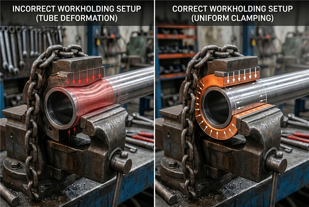
Rigid workholding prevents dangerous movement during high torque application. Heavy chain vises easily crush thin-walled 45# steel cylinder tubes. This excessive clamping pressure induces permanent tube ovality. Ovality destroys the internal piston seal contact line instantly.
Mechanics must use contoured copper cradles inside the vise jaws. The soft copper cradle spreads clamping force across the barrel OD. This uniform distribution protects the carbon steel tube from deformation. Alternatively, mount the cylinder onto a heavy hydraulic teardown bench.
The Operational Divide: Field Removal vs. Shop-Level Repair
| Technical Parameter | Field Removal Limitations | Shop-Level Repair Advantages |
| Thermal Equipment | Field mechanics lack induction heating tools. They use open gas torches instead. | Electric induction coils provide controlled uniform heating to 250°C. |
| Contamination Control | Outdoor wind introduces airborne dust. Field work creates high contamination risks. | Clean shop environments isolate components. Heavy plugs shield the H7 barrel ID. |
| Workholding & Torque | Mechanics use improvised poor workholding setups. Manual spanners slip easily under force. | Heavy-duty automated teardown benches generate 50,000 ft-lbs of smooth torque safely. |
| Thread Protection | Uneven flame heat warps Grade 65-45-12 ductile iron threads. | Controlled cooling cycles maintain the original H7 precision tolerance fit. |
| Post-Removal Inspection | Field workers use manual visual checks. Visual inspection misses micro-tears. | Precision metrology testing equipment verifies the internal tube roundness instantly. |
Advanced Escalation Procedures
Chemical Capillary Dissolution
Standard oil cannot penetrate a frozen cylinder thread. You must apply industrial penetrating solvent with low viscosity. Thermal cycling helps the capillary action. Heat the barrel to 80°C. Then spray the penetrating fluid into the thread gap. The cooling metal pulls the fluid deep inside. Allow a total soak time of four hours. This timing dissolves hardened rust crystals completely.
Thermal Expansion (Breaking the Bond)
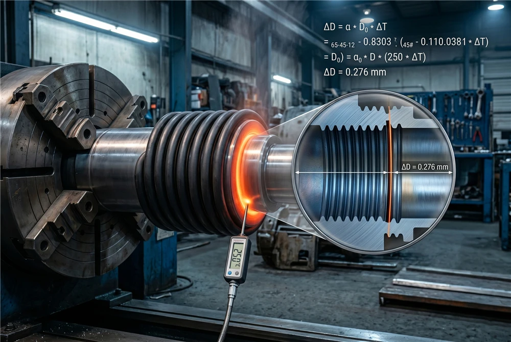
Localized induction heating expands the barrel tube. The inner gland remains cool. This temperature difference creates a micro-gap between the cylinder threads. Target a precise temperature of 250°C. This specific heat breaks down factory anaerobic threadlockers. The high heat reduces the glue shear strength to zero.
Here is the technical expansion formula for a 100mm 45# steel barrel:
D0 equals the original barrel thread diameter. α represents the thermal expansion coefficient of 45# steel. This value is 12 × 10−6 per degree Celsius. ΔT is the temperature change of 230°C. The calculation yields a clearance increase of 0.276 mm.
This micro-gap frees the frozen Grade 65-45-12 ductile iron threads instantly.
Mechanical Shock & Micro-Vibrations
Do not strike the steel cylinder components with a steel hammer. Steel hammers dent the 45# barrel wall. Denting destroys the H7 precision internal tolerance. Instead, place a blunt brass drift against the gland face. Strike the brass drift with a two-pound hammer.
Alternatively, use a pneumatic chipping hammer with a blunt tip. Set the air pressure to 90 PSI. Apply micro-vibrations around the perimeter of the cylinder head. The rapid vibrations fracture the rigid iron oxide crystals safely.
Wire-Ring Style Extraction
Wire-ring cylinders require a specific mechanical trick for gland removal. Rust often jams the wire ring inside its internal groove. You cannot pull the gland out while the wire stays locked. Use a hydraulic ram to push the gland deeper. Press the gland exactly 3mm into the barrel bore.
This motion clears the hidden wire ring groove completely. Now the wire ring expands into the open clearance space. Insert a sharp steel pick into the side access hole. Hook the end of the spring wire ring. Pull the wire out through the slot while rotating the rod.
Technical Risk Management: Damage Thresholds
Operational Red Lines During Gland Extraction
Technicians must monitor physical structural changes during the removal process. Exceeding factory thresholds causes permanent component destruction. Use the matrix below to establish clear operational stop limits.
| Monitored Parameter | Absolute Stop Limit (Red Line) | Immediate Consequence of Failure |
| Gland Pin Hole Shape | Stop if drive hole elongates past 2mm. Measure with digital calipers. | Excessive torque tears the Grade 65-45-12 ductile iron edge completely. |
| Piston Rod Hard Chrome | Stop heating if the chrome surface turns a dull blue color. | Blistering chrome destroys high-pressure polyurethane rod seals instantly. |
| Teardown Bench Torque | Stop the hydraulic pump at 15,000 ft-lbs of total torque. | Extreme force strips internal H7 thread tracks permanently. |
| Barrel Tube Profile | Stop when the barrel OD expands by 0.35mm during heating. | The carbon steel tube loses its original tensile pressure rating. |
Salvage Operations
Machining New Engagement Points
Sheared factory drive holes leave the gland immovable. Mechanics must machine new engagement points. Mount the ductile iron gland on a milling machine index head. Rotate the component exactly 180 degrees away from the damaged holes. Drill fresh 12mm heavy-duty drive holes into the solid metal. This location avoids the structurally compromised areas. The new holes allow full spanner wrench engagement safely.
The Welded Bar/Nut Method
Extreme seizure requires the sacrificial welded hex block method. Place a heavy carbon steel hex nut onto the gland face. Weld the nut circumference using an E7018 low-hydrogen electrode. The intense welding arc delivers deep localized heat. This rapid thermal shock shatters the internal iron oxide crystals. The heat breaks the chemical galling bond instantly. Fit a heavy-duty impact socket over the welded hex block. Apply pneumatic force to turn the seized gland out.
Sacrificial Boring
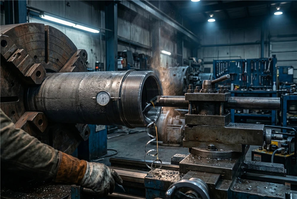
Total thread cold-welding ruins both components during forced rotation. You must protect the expensive custom barrel tube. Sacrificial boring saves the long-lead-time cylinder tube. Mount the entire cylinder barrel onto a C6150 lathe chuck. Align the center axis perfectly with a dial indicator.
Boring bars machine away the destroyed ductile iron gland completely. Stop cutting right before the internal barrel thread peaks. Peel the remaining metal foil out with hand tools. This destructive action completely preserves the costly factory barrel tracks.
Post-Removal Inspection & Metrology
Post-Removal Quality Control Matrix
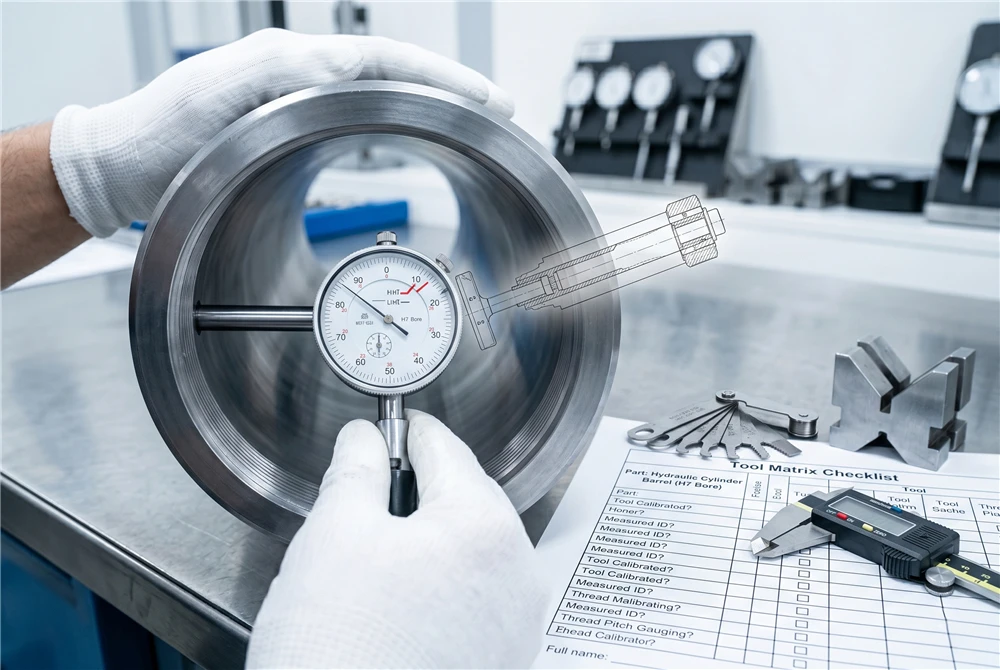
Technicians must conduct dimensional metrology right after gland extraction. Standard visual checks miss micro-structural failures. Use calibrated workshop instruments to verify component serviceability.
| Metrology Zone | Factory Tool & Operational Action | Critical Defect & Scrap Criterion |
| Gland & Barrel Threads | Press thread pitch gauges against the Grade 65-45-12 ductile iron tracks. | Scrap the component immediately if threads stretch or show micro-tears. |
| Cylinder Barrel Bore | Insert dial bore gauges deep inside the 45# steel tube. Measure at three depths. | Reject the barrel if the internal diameter exceeds original H7 tolerance limits. |
| Piston Rod Alignment | Place the 45# steel piston rod onto precision v-blocks. | Reject the rod if the dial indicator shows any side-load bending. |
| Rod Surface Finish | Inspect the hard chrome surface under high optical magnification. | Replace the rod if microscopic chrome scoring risks cutting new polyurethane seals. |
OEM Specifications & Reassembly Engineering
Thread Form Identification
Identify the specific thread form before reassembly. Standard industrial cylinders use standard UN/UNF threads. Heavy machinery often utilizes metric trapezoidal profiles. Extreme-duty applications require rugged ACME profiles.
Surface Finish Metrology
Measure the surface finish metrology with a calibrated profilometer. The piston rod requires a smooth Ra 0.4 finish. Gland seal grooves require a micro-finish of Ra 0.8. Rough surfaces tear the rubber seal lips during cycle movements.
Material Hardness & Metallurgy
Inspect induction-hardened glands for surface micro-cracking. Plated threads prevent corrosion inside open work environments. Check the material hardness with a portable Rockwell tester.
Pressure Class Alignment
Match machining tolerances with the specific cylinder pressure class. Standard industrial units operate safely at 3000 PSI. Severe applications run at 5000 PSI constant pressure. Heavy-duty mill-duty cylinders require thick-walled forge steel components.
Gland Torque Specifications Matrix (12-UN Heavy-Duty Series)
| Nominal Thread Size & Pitch | Lubrication State: Clean Oiled | Lubrication State: Nickel Anti-Seize |
| 1.500″−12 UN | Apply 450 ft-lbs torque. | Lower torque to 315 ft-lbs. |
| 2.000″−12 UN | Apply 900 ft-lbs torque. | Lower torque to 630 ft-lbs. |
| 2.500″−12 UN | Apply 1500 ft-lbs torque. | Lower torque to 1050 ft-lbs. |
| 3.000″−12 UN | Apply 2200 ft-lbs torque. | Lower torque to 1540 ft-lbs. |
| 3.500″−12 UN | Apply 3100 ft-lbs torque. | Lower torque to 2170 ft-lbs. |
| 4.000″−12 UN | Apply 4300 ft-lbs torque. | Lower torque to 3010 ft-lbs. |
| 4.500″−12 UN | Apply 5800 ft-lbs torque. | Lower torque to 4060 ft-lbs. |
| 5.000″−12 UN | Apply 7600 ft-lbs torque. | Lower torque to 5320 ft-lbs. |
| 5.500″−12 UN | Apply 9800 ft-lbs torque. | Lower torque to 6860 ft-lbs. |
| 6.000″−12 UN | Apply 12500 ft-lbs torque. | Lower torque to 8750 ft-lbs. |
| 7.000″−12 UN | Apply 19500 ft-lbs torque. | Lower torque to 13650 ft-lbs. |
| 8.000″−12 UN | Apply 28000 ft-lbs torque. | Lower torque to 19600 ft-lbs. |
Engineering Note: Threaded gland designs maximize efficiency up to 8.000 inches. Custom cylinders exceeding 8.000 inches transition to bolted flange designs. This transition prevents thread galling during high-torque assembly.
Thread Compound Engineering
Select the correct thread compound based on OEM service charts. Use medium-strength blue anaerobic threadlockers for standard glands. High-strength red glue secures heavy-duty external caps. Apply nickel-based anti-seize on high-temperature steel tracks.
Seal Entry Protection
Pay close attention to seal entry protection protocols. Face the U-cup seal lips toward the high-pressure fluid side. Install chamfered sizing sleeves over sharp rod threads. The metal sleeve prevents seal lip tearing during re-entry.
FAQs
Q1: How do I distinguish blue vs. red threadlocker without damaging my 45# steel barrel?
Set your digital heat gun to 150°C. Apply heat to the joint and attempt to turn it. Blue anaerobic glue softens fully at this temperature. If the gland remains locked, you have high-strength red locker. Increase the target heat to 250°C safely now. This step-by-step heating protocol protects your 45# steel barrel from thermal warping.
Q2: How can I guarantee perpendicularity to the center axis when remachining my deformed gland pin holes?
Mount your deformed gland onto a precision lathe mandrel. Align the original machined face with a sensitive dial indicator. Turn the outer profile until the face runs completely true. This setup guarantees 90-degree perpendicularity to the center axis.
Q3: How do I protect my internal polyurethane seals from melting during thermal disassembly?
Wrap your exposed cylinder barrel with water-cooled induction coils. Direct the thermal energy exclusively onto the thread joint line. Apply a wet freezing rag over the internal seal zones. Keep the internal seal temperature below 80°C.
Q4: Why must I lower my torque wrench setting when I apply anti-seize? By how much?
Anti-seize lubricants significantly reduce thread friction coefficients. Lower friction increases the axial clamp load under equal torque. You must lower the OEM torque spec by exactly 30 percent. Over-tightening stretches the 45# steel thread tracks.
Q5: My cylinder uses ACME threads instead of UN threads. Does this change my force limit during a seize?
Yes. Standard UN threads feature a wide 60° angle. This wide angle generates massive radial wedging forces during a seize. The radial force swells your cylinder barrel tube. Your ACME threads feature a steep 29° angle. ACME profiles convert torque into straight axial thrust instead. This steep angle jams the threads axially like a solid wedge.
Need Factory-Level Evaluation? Send Us Your Drawings
DREJEX analyzes custom hydraulic cylinder head drawings daily. We verify tolerances and material compatibility. Send your technical prints directly to [email protected]. We will review every file securely. Get an expert manufacturing evaluation within 24 hours.